GSRV03 – Gonio Ways
★ High rigidity and high loads
★ Identical locations of rotation centers
★ Low friction and accurate movement
★ Easy installation
★ Low noise
|
Model No. |
GSRV0370-90-11G |
GSRV0370-110-10G |
GSRV03100-160-14G |
||
|
Specification |
Gonio Sliding Range |
± 10° | |||
|
Roller Dia. (D) (mm) |
3 | ||||
|
Roller Number (G) |
11 | 10 | 14 | ||
|
Main Dimensions |
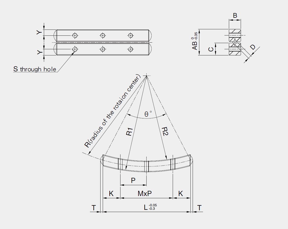
L (mm) |
70 | 100 | ||
|
R (mm) |
90 | 110 | 160 | ||
|
R1 (mm) |
94 | 114 | 164 | ||
|
R2 (mm) |
86 | 106 | 156 | ||
|
AB (mm) |
18 | ||||
|
B (mm) |
8 | ||||
|
C (mm) |
8.5 | ||||
|
Weight Per Set (g) |
135 | 131 | 191 | ||
|
Allowable Load (F) (N) |
1820 | 1800 | 2600 | ||
|
Basic Capacity |
Static Load (C0) (N) |
5480 | 5600 | 7870 | |
|
Dynamic Load (C) (N) |
2620 | 2420 | 2840 | ||
|
θ° |
45.7° | 37° | 36.3° | ||
|
T (mm) |
1.9 | ||||
|
S |
M3 | ||||
|
Y (mm) |
3 | ||||
|
K (mm) |
12.5 | ||||
|
M x P (mm) |
3 x 15 | 5 x 15 | |||
| Product Introduction |
| ♦ Gonio Ways
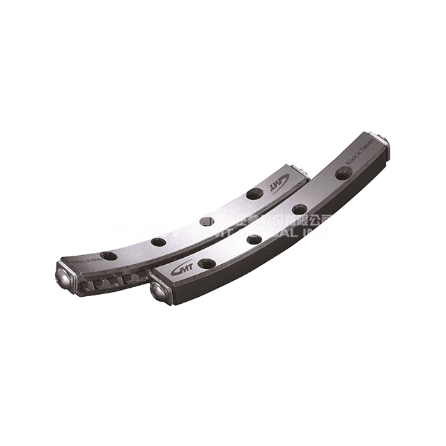
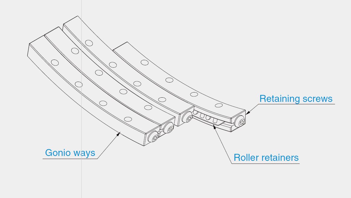
Gonio Ways are non-circulating arc movement rails whose precise cross rollers have extremely low friction resistance to provide a stable arc movement. They are mainly used in locating operations where rotation centers remain unchanged and correct changes of tilting degrees are required, they may also be applied to meet the purposes of optical instruments and measuring devices requiring high accuracy. ♦ Product Structure GSRV model of gonio ways are made up of precisely ground V-shaped rail and retainers equipped with crossed rollers.
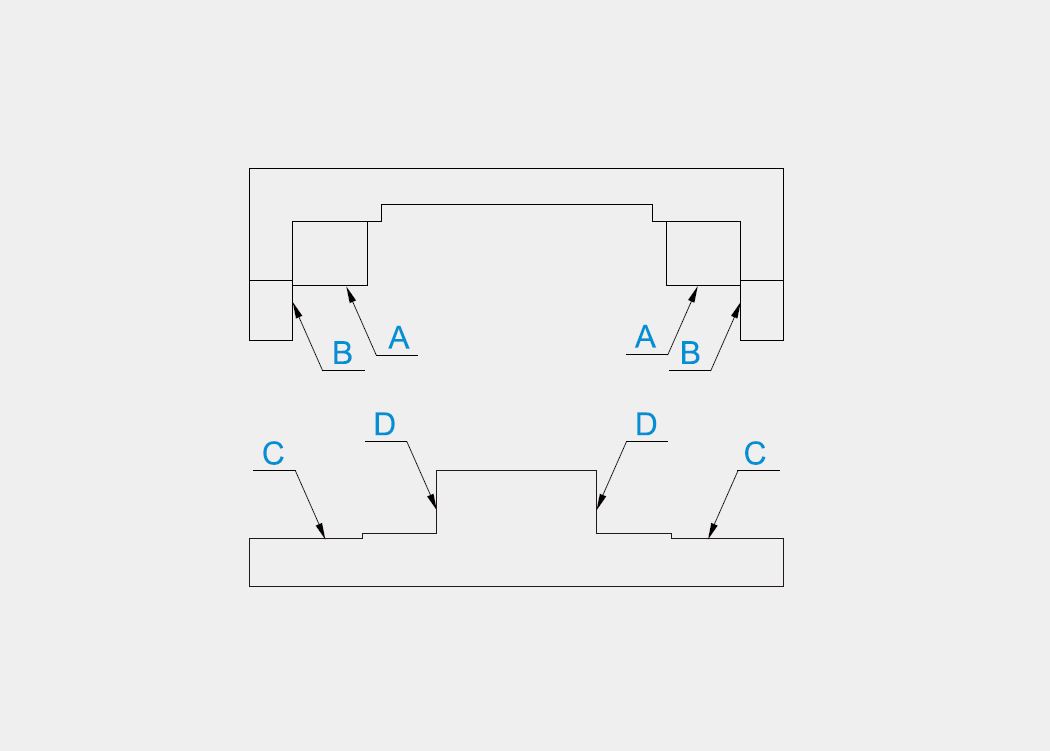
♦ Product Installation Accuracy of the installation surface as shown as below picture, surface A, B, C, D accuracy will directly affect the movement accuracy of gonio ways.
♦ Product Specification One set of GSRV models contains 4 gonio way rails, 2 roller retainers and 8 retaining screws.
♦ Precaution – Lubrication of Retainers:Use lithium soap based lubricating grease. – Deviation of Retainers:Retainers will deviate from their correct positions when gonio ways are used under conditions of high speed, vibrations and unbalanced loads. – Dust-Proof:Gonio ways may not realize their ideal performance due to dust or foreign objects likely to penetrate into their interior depending on operating environment. It is recommended to protect gonio ways by using external dust-proof covers on them if they are to be used in harsh environments. – Damping Boards:Screws are installed on the end faces of the gonio ways to prevent the retainers falling. – Environment for Using Gonio Ways:It is recommended to use our gonio ways in environments with temperature ranging from -20° to 110°. – Using a Paired Set Is a Principle:The accuracy for using gonio ways is based on the unit of a complete set to realize a precise control on – Adjustments:When used under such circumstances where the accuracy on the installation face or the pre-load has not been fully adjusted, their movement accuracy will drop, thus resulting in the deflection or distortion and rendering it likely to reduce their use performance and life, exercise extreme caution during adjustment. – Allowable Load:Please refer to the highest values of loads when the total flexible distortion on the contact parts remains small and a smooth rolling can still be performed under the maximal contact stress on the rolling body and rail surface. |
| Installation Sequence |
| 1. Firstly, clean the sliding ways and the installation surface on the seat to prevent the entry of foreign objects during installation.
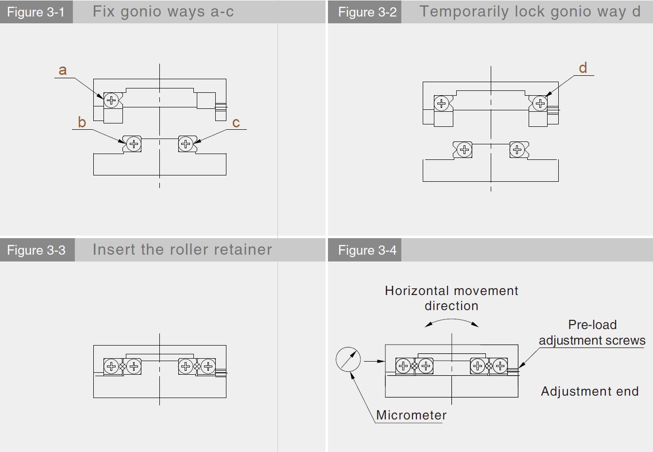
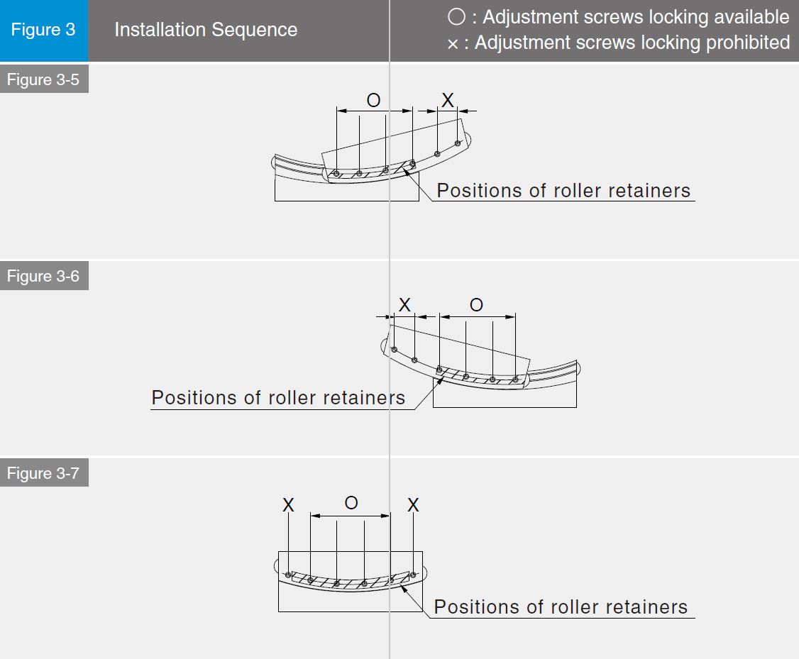
2. Apply low viscocity lubricant onto each installation surface and lock gonio ways a, b, c to each surface intallation by using the suggested torque force.(Figure 3-1) 3. Temporarily lock gonio by way d.(Figure 3-2) 4. Remove the retaining screws from any end and insert the roller retainers into the central position of the gonio way, upon the completion of the above operations, restore the screw to its original position.(Figure 3-3) 5. Try moving the sliding way horizontally to its maximal traveling end and adjust the roller retainer to its central position.(Figure 3-4) 6. Install a micrometer at the side of the sliding way base level.(Figure 3~4). 7. Move the sliding way to the traveling end at any side and slightly lock pre-load adjustment screw above the roller retainer.(Figure 3-5) 8. Move the sliding way to the traveling end at the other side and slightly lock pre-load adjustment screw.(Figure 3-6) 9. Move the sliding way to the central position and slightly lock the adjustment screw at the central position.(Figure 3-7) 10. Repeat operations from (7) to (9) until there is no backlash when moving the slide. Caution against applying excessiye pre-load. 11. Once there is no back lash in moving direction, the micromer reading is minimal and stable when the sliding way is moving, at this time, carry out final calibration of the pre-load by repeating operations from (7) to (9) by the torque force recommended to lock. 12. Tighten the gonio way d which has been temporarily locked per pre-load adjustment screws in sequence locking available. |







Reviews
There are no reviews yet.